Night Vision Monocular: Step-by-Step Component Guide
How to Assemble a PVS-14
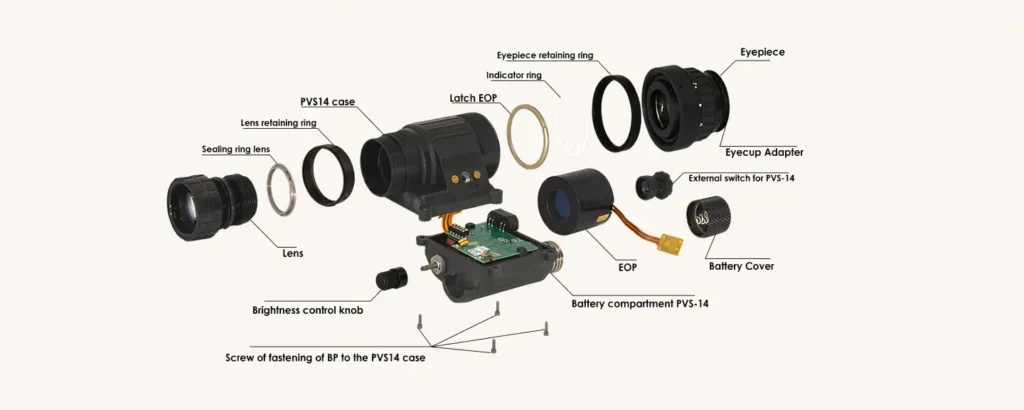
The PVS-14 is one of the most widely used modular night vision monocular designs. Its structure usually includes a front objective lens, rear ocular lens, image intensifier tube, main housing, battery compartment, light pipe, circuit connection, and retaining screws. Proper assembly is important because even a small alignment error, loose contact, or dust inside the optical path can affect image clarity and device reliability.
This guide introduces the general assembly process of a PVS-14 night vision monocular from a component-level perspective. It is intended for professional reference, product education, and technical understanding.
1. Main Components Required for PVS-14 Assembly
Before assembly, the main components should be prepared and checked carefully.
| Component | Function |
|---|---|
| PVS-14 housing | Holds the optical, electronic, and power components |
| Objective lens | Collects available light from the environment |
| Ocular lens | Allows the user to view the intensified image |
| Image intensifier tube | Converts low-light input into a visible image |
| Tube lock ring | Secures the image intensifier tube inside the housing |
| Objective lock ring | Fixes the objective lens position |
| Light pipe | Transfers indicator light inside the housing |
| Circuit board / leads | Connects power and control functions |
| Battery housing | Supplies power to the device |
| Retaining screws | Locks the upper and lower housing sections together |
All parts should be clean, dry, and compatible with the same PVS-14 housing standard.
2. Preparing the Housing Before Assembly
The housing should be inspected before installing any optical or electronic parts. Check the screw holes, battery interface, sealing areas, and internal contact points. Any dust, oil, or foreign object inside the housing may affect image quality or electrical performance.
It is also important to confirm that the housing is not cracked or deformed. A damaged housing may cause poor sealing, unstable alignment, or loose internal components.
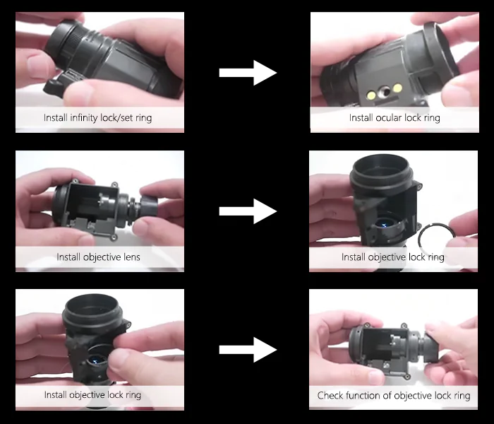
3. Installing the Objective Lens
The objective lens is installed at the front of the PVS-14 housing. During installation, the lens should be aligned with the front thread and rotated smoothly into position. The lens should not be forced, as damaged threads may affect future focusing adjustment.
After the lens is installed, the objective lock ring is used to secure its position. The lock ring should hold the lens firmly while still allowing proper focus adjustment.
4. Checking the Objective Focus Ring
After installing the objective lens and lock ring, the focus ring should be checked. It should rotate smoothly without obvious looseness or resistance. The focusing range must be enough for near and distance viewing.
If the focus ring is too tight, it may be difficult to adjust in real use. If it is too loose, the focus may shift during movement.
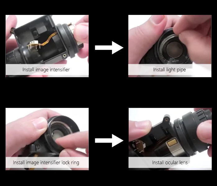
5. Installing the Light Pipe
The light pipe is a small but important part of the PVS-14 structure. It helps transfer internal indicator light, such as IR or low-battery signals, to the correct viewing position.
When installing the light pipe, make sure it is seated in the correct channel and not blocked by other parts. Incorrect placement may cause the indicator function to fail or appear weak.
6. Installing the Image Intensifier Tube
The image intensifier tube is the core component of the PVS-14. It should be handled carefully and kept away from dust, fingerprints, and impact.
When placing the tube into the housing, the tube orientation and electrical contact position must be correct. The input and output windows should not be touched directly. After the tube is seated properly, the tube lock ring is installed to secure it inside the housing.
The tube should be stable, but the lock ring should not be overtightened. Excessive pressure may affect the tube or housing structure.
7. Installing the Ocular Lens
The ocular lens is installed at the rear of the housing. This part allows the user to view the intensified image and adjust diopter focus according to eyesight.
After installation, the ocular lens should rotate smoothly. The rear optical path should remain clean and free from dust.
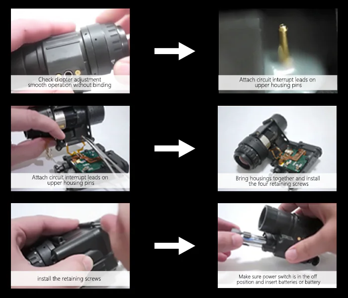
8. Connecting the Circuit Leads
The circuit connection is responsible for power and control functions. In a typical PVS-14 assembly, the circuit leads must align correctly with the housing pins and battery system.
Before closing the housing, check that the wires or contact leads are positioned properly. They should not be bent, compressed, or trapped between the upper and lower housing sections. Poor contact may cause power failure, flickering, or unstable operation.
9. Closing the Housing
Once the optical and electronic parts are installed, the housing can be closed. The upper and lower sections should fit together evenly.
Install the retaining screws and tighten them gradually. A balanced tightening sequence is recommended to avoid uneven pressure on the housing. Do not overtighten the screws, as this may damage the plastic housing or affect sealing.
10. Installing the Battery Housing and Battery
After the main body is assembled, install the battery housing and battery cap. Before inserting the battery, make sure the power switch is in the OFF position.
Check the battery polarity carefully. Incorrect battery installation may prevent the device from powering on or damage internal components.
11. Initial Power-On Test
After assembly, the PVS-14 should be tested in a suitable low-light environment. The first test should confirm whether the device powers on normally and whether the image appears stable.
Key test points include:
| Test Item | What to Check |
|---|---|
| Power-on function | Device turns on normally |
| Image clarity | No serious blur, shadow, or distortion |
| Focus adjustment | Objective and ocular focus work smoothly |
| Indicator function | IR or low-battery indicator works if supported |
| Electrical stability | No flickering or intermittent power loss |
| Housing fit | No obvious gap, looseness, or abnormal sound |
If the image is unstable or the device fails to power on, the circuit contacts, battery position, and tube seating should be checked again.
12. Common Assembly Mistakes to Avoid
Several common mistakes may affect the performance of a PVS-14 monocular:
| Mistake | Possible Result |
|---|---|
| Image intensifier tube installed in the wrong direction | No image or abnormal output |
| Dust inside the optical path | Black spots or reduced image clarity |
| Loose circuit contact | Flickering or power failure |
| Objective lock ring too tight | Difficult focus adjustment |
| Retaining screws tightened unevenly | Housing gap or poor sealing |
| Battery polarity error | Device cannot power on |
| Wires compressed by housing | Electrical instability |
Conclusion
Assembling a PVS-14 night vision monocular requires careful handling of optical, electronic, and mechanical components. The most important steps include correct objective lens installation, proper image intensifier tube placement, reliable circuit connection, even housing closure, and complete final testing.
For manufacturers, distributors, and technical buyers, understanding the PVS-14 assembly structure also helps evaluate product quality, serviceability, and component compatibility. A well-assembled PVS-14 should provide stable imaging, smooth focusing, secure housing, and reliable field performance.